 +1 (855)
 Blog
Can consumer AI troubleshoot networks?
Members of the IPA team were pleased to assist NANOG 94, where we found lots of food, excellent drinks, great friends and colleagues, and state-of-the-art talks on many topics related to networking. This edition was focused on datacenters, protocols, automation,...

Unveiling BueNOS 3.1: The Next Frontier in Network Operating Systems
In the ever-evolving landscape of technology, the demand for efficient and reliable network management systems has never been higher. Meet BueNOS 3.1 – the groundbreaking solution poised to revolutionize the way organizations manage their networks. What is BueNOS 3.1?...

Building 100Gig Core with EVPN and Segment routing
Over the past few years, a number of internet Service Providers (ISPs) have upgraded to 100 Gigabit core networks. Many have found success using Mikrotik on the path to 100Gb core using Layer 2 VPN technology like VPLS. With the proper hardware and design, this...
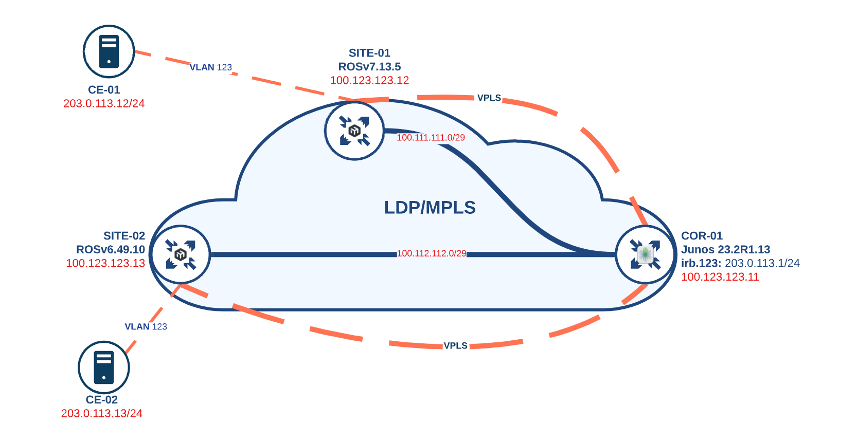
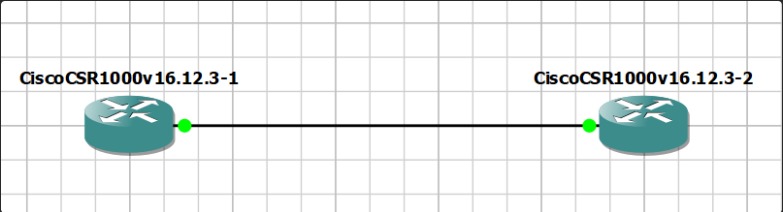
JunOS and RouterOS LDP InterOP
Virtual Private LAN Service (VPLS) is one of the most widely used components to extend layer 2 domains for disparate locations in Service Provider environments. VPLS creates an emulated 'Pseudo-LAN' by combining Layer 2 ethernet and Label Switched Paths. In network...
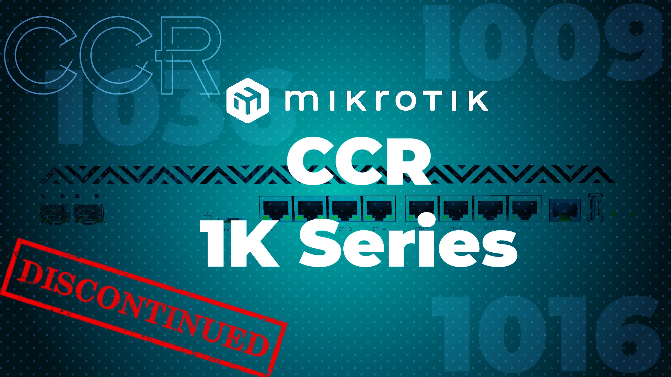
MikroTik CCR 1009/1016/1036 officially discontinued
We knew it was coming when MikroTik announced the end of production for Tilera chips back in the fall of 2022, but recently (looks like it was last week), MikroTik moved almost all of the CCR1K series (CCR1009, CCR1016, CCR1036) to discontinued officially on the...
MikroTik RouterOS v7.11 stable released
2023 has been a big year for MikroTik RouterOS v7 development. The OS has matured quite a bit and the number of operators that are using ROSv7 in prod has gone up significantly. Most of the work this year has been centered around...
MikroTik introduces Back to Home (bth) VPN in ROS 7.11 beta/rc
Back To Home - RouterOS - MikroTik DocumentationMikroTik already has a wealth of VPN options and is introducing another with the Back to Home or BTH VPN service. The framework underneath is based on wireguard which MikroTik began supporting in the early 7.x series of...
EVPN-Multihoming over MPLS w/IP Infusion’s OcNOS to netElastic’s vBNG for subscriber management
Having highly available layer-2 uplinks in a service provider has been around for a long time and there have been various ways to do it over the years, multi-chassis lag, stacking, active passive pseudowires, and more. If you use traditional VPLS and dual home a...
A simplified – cost effective – way to deliver IPTV with IP Infusion
Multicast used to be the defacto standard for delivering IPTV and a lot of legacy IPTV systems are still fully based on multicast or require sending local channels via multicast to a large provider to get the stream back for unicast delivery to clients. This has only...
WEBINAR: Validated MX204 Alternatives: IP Infusion OcNOS
We recently did a webinar on alternatives to Juniper Network's MX204 platform. While the MX204 was a fully capable router it was End Of Life'd and then recently the EOL was revoked after approximately a year. During the period before the end of life revocation...