 +1 (855)
 Multicast used to be the defacto standard for delivering IPTV and a lot of legacy IPTV systems are still fully based on multicast or require sending local channels via multicast to a large provider to get the stream back for unicast delivery to clients. This has only been sped up by home users cancelling traditional cable and moving to things like roku, hulu live, apple tv, and then insert your streaming service of choice here.
In many networks, it is no longer advantageous or necessary to use complex mLDP and MVPN to deliver multicast traffic given the larger capacity of the links and reduced multicast traffic.
We’ve put in a lot of IPTV solutions and almost always outside of the content providers themselves, a centralized headend for delivery works well. This means building traditional VPLS tunnels back to the video source. It is simple, works well, and easy to maintain in comparison to mLDP, P2MP, and MVPN. Granted it does not scale as well as mLDP/MVPN but most tier 2 and tier 3 providers are not operating at a scale where the limits are met.
Additionally, to get these protocols it often means expensive hardware to deliver a complex solution.
Lets explore a solution put together with whitebox hardware; edgecore and ufispace running IP Infusions OcNOS SP 6.0.2.
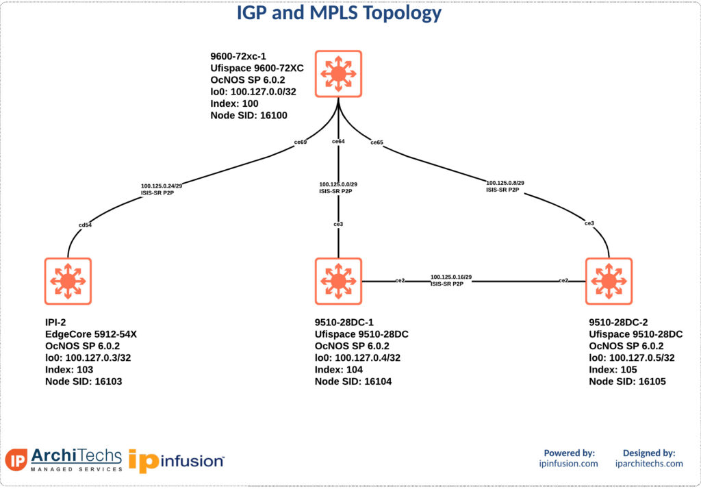
IGP and MPLS Topology
This example utilizes LDP signaled VPLS running on top of ISIS-SR.
VPLS Topology
We’re running LDP signaled VPLS for service delivery. The latest version of OcNOS has also fixed the dependency of having to run LDP on an interface to operate LDP VPLS over SR-MPLS. This allows for easier overall configuration with less overhead in the cli.
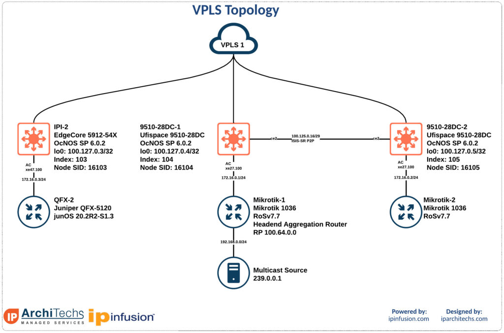
We are going to statically join the group 239.0.0.1 on the multicast receivers; QFX-2, Mikrotik-1, and Mikrotik-2. Then we will send from the source 192.168.0.2 to group 239.0.0.1 utilizing iperf and verify receipt of traffic.
First lets look at the VPLS tunnels and verify they are up. We aren’t going to verify on every router.
9510-28DC-2#show run mpls
!
mpls vpls LDP 1
 signaling ldp
  vpls-peer 100.127.0.3
  vpls-peer 100.127.0.4
  exit-signaling
 exit-vpls
!
router ldp
 router-id 100.127.0.5
 targeted-peer ipv4 100.127.0.3
  exit-targeted-peer-mode
 targeted-peer ipv4 100.127.0.4
exit-targeted-peer-mode9510-28DC-2#show mpls vpls detail
Virtual Private LAN Service Instance: LDP, ID: 1
SIG-Protocol: LDP
Attachment-Circuit :UP
Learning: Enabled
Control-Word: Disabled
Flow Label Status: Disabled, Direction: None, Static: No
Group ID: 0, VPLS Type: Ethernet, Configured MTU: 1500
Description: none
service-tpid: dot1.q
Operating mode: Raw
Configured interfaces:
Interface: xe27.100
Subinterface Match Criteria(s) :
dot1q 100
Interface: ce2.100
Subinterface Match Criteria(s) :
dot1q 100
Mesh Peers:
100.127.0.3 (Up)
100.127.0.4 (Up)9510-28DC-2#show mpls ldp session
Peer IP Address IF Name My Role State KeepAlive UpTime
100.127.0.4 ce2 Active OPERATIONAL 30 3d23h31m
100.127.0.3 ce3 Active OPERATIONAL 30 3d23h32m9510-28DC-2#show mpls vpls mac-address name LDP
MAC address Learned from Vlan-Id Peer address Time-out
000c.42b2.a63c ce2 - 100.127.0.4 300
4c5e.0c23.df4e xe27.100
84c1.c132.5032 ce3 - 100.127.0.3 300So now we can see that targeted sessions up, attachment circuit up, and local/remote mac addresses learned across the circuit. Lets move on to multicast verification.
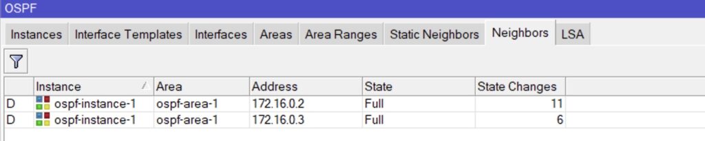
First we’ll verify that routing over OSPF is up and reachability then PIM.
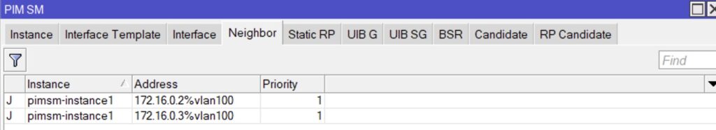
Here is the RP and the PIM DR for the routers connecting over the VPLS tunnels.
and for people that like the CLI.
[email protected]# run show pim neighbors
B = Bidirectional Capable, G = Generation Identifier
H = Hello Option Holdtime, L = Hello Option LAN Prune Delay,
P = Hello Option DR Priority, T = Tracking Bit,
A = Hello Option Join Attribute

Instance: PIM.master
Interface           IP V Mode        Option       Uptime Neighbor addr
xe-0/0/47.100        4 2             HPLGT       05:04:56 172.16.0.1
xe-0/0/47.100        4 2             HPLGT       05:03:43 172.16.0.2

{master:0}[edit]
[email protected]# run show ospf neighbor
Address          Interface              State           ID               Pri  Dead
172.16.0.2       xe-0/0/47.100          Full            172.16.0.2       128    35
172.16.0.1       xe-0/0/47.100          Full            192.168.0.1      128    35
Lets verify that we got the s,g entry and the multicast traffic on the receivers. We will look at the torch output on mikrotik-2 to see the inbound traffic.
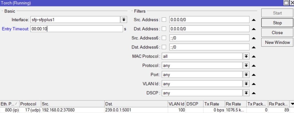
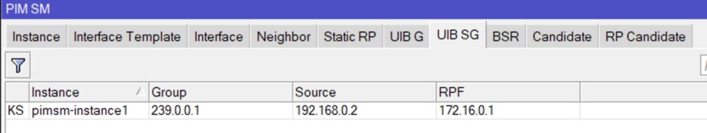
[email protected]# run show multicast route
Instance: master Family: INET

Group: 239.0.0.1
    Source: 192.168.0.2/32
    Upstream interface: xe-0/0/47.100
As seen above we have the appropriate entries for the group and inbound traffic.
Conclusion
It is possible and often better to deploy a simple solution using MPLS and VPLS overlayed on top for multicast delivery. This is simple to deploy, troubleshoot, and maintain. This same principle can be extended with EVPN for a layer 2 overlay with either MPLS or VxLAN data plane. This extensibility makes the solution future proof and easy to migrate as the underlying service or transport changes.
We’ve worked with ISPs on IPTV deployments using L2VPN into the tens of thousands of receivers with the correct planning considerations.
Please look for future blog posts for scaling multicast in large networks or working with multicast in a bandwidth-constrained environment.