Virtual Private LAN Service (VPLS) is one of the most widely used components to extend layer 2 domains for disparate locations in Service Provider environments. VPLS creates an emulated ‘Pseudo-LAN’ by combining Layer 2 ethernet and Label Switched Paths. In network engineering, you are at times faced with multi-vendor scenarios that place a demand on interoperability or cross compatibility on different Network Operating Systems (NOS). A couple of reasons or scenarios on the backdrop of inter-operations between NOS includes but is not limited to:
For the current level of business, you may not have the muscle to put a vendor of choice everywhere, so you start with critical components like in the core and use another vendor downstream.
You don’t want vendor-lock
Migration – in most cases it is not feasible to do a network overhaul and make NOS changes across the entire infrastructure at once or overnight.
Other vendors excel in specific network functions more than others.
A centralized BNG architecture.
In this blog I present a simple configuration template for LDP signaled VPLS interop between Junos 23 and Mikrotik versions 6.49.10 and 7.13.5. I used container lab for the LAB. The Juniper vMX is acting as a centralised BNG and the Mikrotiks as Provider Edge routers.

Configuration
Not all configurations are shown. The assumption is that the IGP and other configuration is already working.
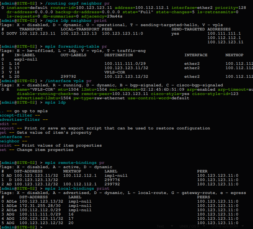
NB. VPLS MTU is set 1504 to compensate for the VLAN Tag on all routers in the VPLS instance.
#Junos COR-01
# Configuration group - This simplifies repeated statements in configuration and creates smaller and more logically constructed configuration files

groups {
  ospf-cfg {
    protocols {
      ospf {
        area <*> {
          interface <*> {
            interface-type p2p;
            bfd-liveness-detection {
              minimum-interval 300;
              multiplier 3;
...

# Interface configuration - Dont forget family MPLS for PE facing interfaces.

  interfaces {
    ge-0/0/0 {
      unit 0 {
        description LINK-SITE-01;
        family inet {
          address 100.111.111.1/29;
      }
        family mpls;
    }
}
    ge-0/0/1 {
      unit 0 {
        description LINK-SITE-02;
        family inet {
          address 100.112.112.1/29;
      }
        family mpls;
    }
}
    irb {
      unit 123 {
        description CE-GW;
        family inet {
          mtu 1500;
          address 203.0.113.1/24;
      }
  }
    lo0 {
      unit 0 {
        family inet {
          address 100.123.123.11/32;
    }
# Just for fun threw a little bit of DHCP in the mix.
access {
  address-assignment {
    pool DHCP-POOL {
      family inet {
        network 203.0.113.0/24;
        range DHCP-POOL {
          low 203.0.113.10;
          high 203.0.113.20;
}
        dhcp-attributes {
          name-server {
            1.1.1.1;
            9.9..9.9;
    }
          router {
            213.0.113.1;
    }
}
...

# For the VPLS instance, if you need cross communication within a single VPLS domain you need the mesh-group and local switching stanzas. If not Just use the neighbor stanza and that will allow communication from CE to gateway only, essentialy no local-switching and mesh-group isolates CEs.
...
routing-instances {
  VPLS01 {
    instance-type vpls;
    protocols {
      vpls {
        mesh-group VPLS-MESH {
          local-switching;
          neighbor 100.123.123.12;
          neighbor 100.123.123.13;
        }
        encapsulation-type ethernet;
        site-range 10;
        no-tunnel-services;
        vpls-id 123;
        mtu 1504;
        connectivity-type irb;
      }
     vlan-id 123;
     routing-interface irb.123;
 }

# Configure your Protocols, OSPF,LDP and MPLS for the relevant interfaces. The apply-group allows the ospf config lines to inherit bfd and interface type in ospf.

protocols {
  ldp {
    interface ge-0/0/0.0;
    interface ge-0/0/1.0;
    interface lo0.0;
  }
  mpls {
    interface ge-0/0/0.0;
    interface ge-0/0/1.0;
  }
  ospf {
    area 0.0.0.0 {
      interface lo0.0 {
        passive;
  }
      interface ge-0/0/0.0 {
        apply-groups ospf-cfg;
  }
      interface ge-0/0/1.0 {
        apply-groups ospf-cfg;
...SITE-01 (Mikrotik Rosv7.13.5)
add name=Lo0
/interface vpls
add cisco-static-id=123 mtu=1504 name=VPLS-COR-01 peer=100.123.123.11 \
/interface vlan
add interface=VPLS-COR-01 name=VLAN123-VPLS vlan-id=123
/port
set 0 name=serial0
/routing ospf instance
add disabled=no name=INS-OSPF router-id=100.123.123.12
/routing ospf area
add disabled=no instance=INS-OSPF name=AREA-0
/ip address
add address=100.123.123.12 interface=Lo0 network=100.123.123.12
add address=100.111.111.2/29 interface=ether2 network=100.111.111.0
/mpls interface
add input=yes interface=ether2 mpls-mtu=1530
/mpls ldp
add lsr-id=100.123.123.12 transport-addresses=100.123.123.12
/mpls ldp interface
add accept-dynamic-neighbors=yes interface=ether2 transport-addresses=100.123.123.12
/routing bfd configuration
add interfaces=ether2 min-rx=300ms min-tx=300ms multiplier=3
/routing ospf interface-template
add area=AREA-0 disabled=no interfaces=Lo0 networks=100.123.123.12/32 passive
add area=AREA-0 disabled=no interfaces=ether2 networks=100.111.111.0/29 type=ptp use-bfd=yes
/system identity
set name=SITE-01
SITE-01 (Mikrotik Rosv6.49.10)
/interface bridge
add name=Lo0
/interface vpls
add advertised-l2mtu=1504 cisco-style=yes cisco-style-id=123 disabled=no l2mtu=1504 mtu=1504 name=VPLS-COR remote-peer=100.123.123.11
/routing ospf instance
set [ find default=yes ] router-id=100.123.123.13
/ip address
add address=100.123.123.13 interface=Lo0 network=100.123.123.13
add address=100.112.112.3/29 interface=ether2 network=100.112.112.0
/ip dhcp-client
add disabled=no interface=ether1
/mpls interface
add interface=ether2 mpls-mtu=1530
/mpls ldp
set enabled=yes lsr-id=100.123.123.13 transport-address=100.123.123.13
/mpls ldp interface
add interface=ether2 transport-address=100.123.123.13
/routing bfd interface
add interface=ether2 interval=0.3s min-rx=0.3s multiplier=3
/routing ospf interface
add interface=ether2 network-type=point-to-point use-bfd=yes
/routing ospf network
add area=backbone network=100.123.123.13/32
add area=backbone network=100.112.112.0/29
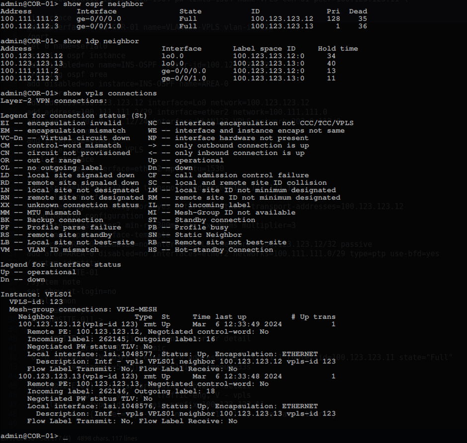
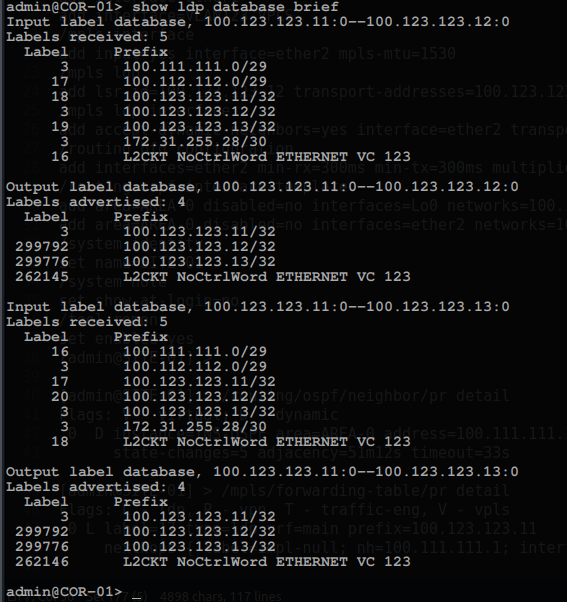
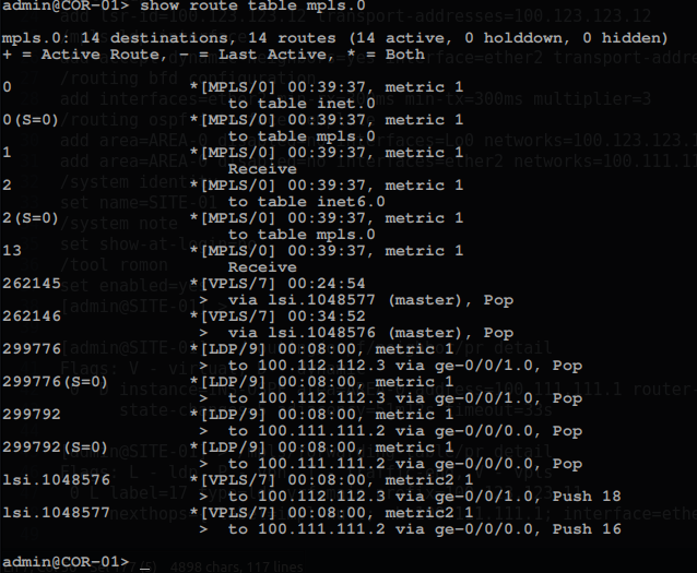
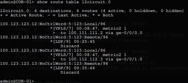
Validation
#JunOS
admin@COR-01> ping 203.0.113.12
PING 203.0.113.12 (203.0.113.12): 56 data bytes
64 bytes from 203.0.113.12: icmp_seq=0 ttl=64 time=0.957 ms
64 bytes from 203.0.113.12: icmp_seq=1 ttl=64 time=1.340 ms
64 bytes from 203.0.113.12: icmp_seq=2 ttl=64 time=1.168 ms
64 bytes from 203.0.113.12: icmp_seq=3 ttl=64 time=1.087 ms
64 bytes from 203.0.113.12: icmp_seq=4 ttl=64 time=1.120 ms
64 bytes from 203.0.113.12: icmp_seq=5 ttl=64 time=1.033 ms
64 bytes from 203.0.113.12: icmp_seq=6 ttl=64 time=1.163 ms
64 bytes from 203.0.113.12: icmp_seq=7 ttl=64 time=1.048 ms
^C
--- 203.0.113.12 ping statistics ---
8 packets transmitted, 8 packets received, 0% packet loss
round-trip min/avg/max/stddev = 0.957/1.115/1.340/0.108 ms
admin@COR-01> ping 203.0.113.13
PING 203.0.113.13 (203.0.113.13): 56 data bytes
64 bytes from 203.0.113.13: icmp_seq=0 ttl=64 time=2.081 ms
64 bytes from 203.0.113.13: icmp_seq=1 ttl=64 time=0.905 ms
64 bytes from 203.0.113.13: icmp_seq=2 ttl=64 time=1.206 ms
64 bytes from 203.0.113.13: icmp_seq=3 ttl=64 time=1.002 ms
64 bytes from 203.0.113.13: icmp_seq=4 ttl=64 time=1.125 ms
64 bytes from 203.0.113.13: icmp_seq=5 ttl=64 time=1.340 ms
64 bytes from 203.0.113.13: icmp_seq=6 ttl=64 time=0.840 ms
64 bytes from 203.0.113.13: icmp_seq=7 ttl=64 time=1.081 ms
^C
--- 203.0.113.13 ping statistics ---
8 packets transmitted, 8 packets received, 0% packet loss
==============================================================
#ROSv7
[admin@CE-01] > /ping 203.0.113.1
SEQ HOST SIZE TTL TIME STATUS
0 203.0.113.1 56 64 416us
1 203.0.113.1 56 64 421us
2 203.0.113.1 56 64 454us
3 203.0.113.1 56 64  387us
4 203.0.113.1 56 64 619us
5 203.0.113.1 56 64 365us
6 203.0.113.1 56 64 680us

[admin@CE-01] > /ping 203.0.113.13
SEQ HOST SIZE TTL TIME STATUS
0 203.0.113.13 56 64 419us
1 203.0.113.1356 64 401us
2 203.0.113.1356 64 450us
3 203.0.113.1356 64  367us
4 203.0.113.1356 64 615us
5 203.0.113.1356 64 368us
6 203.0.113.13 56 64 670us

====================================================================================
#ROSv6

[admin@CE-02] > /ping 203.0.113.1
SEQ HOST SIZE TTL TIME STATUS
0 203.0.113.1 56 64 0ms
1 203.0.113.1 56 64 0ms
2 203.0.113.1 56 64 0ms
3 203.0.113.1 56 64 0ms
4 203.0.113.1 56 64 0ms
5 203.0.113.1 56 64 0ms
6 203.0.113.1 56 64 0ms
7 203.0.113.1 56 64 0ms

[admin@CE-02] > /ping 203.0.113.12
SEQ HOST SIZE TTL TIME STATUS
0 203.0.113.12 56 64  1ms
1 203.0.113.12 56 64  2ms
2 203.0.113.1256 64  0ms
3 203.0.113.1256 64  3ms
4 203.0.113.1256 64  1ms
5 203.0.113.1256 64  0ms
6 203.0.113.1256 64  2ms
7 203.0.113.1256 64  0ms
 +1 (855) 645-7684