 +1 (855) 645-7684
One of the biggest misconceptions I had before moving into the service provider space was that all layer 2 operations had been replaced with layer 3. I quickly found out that even if you are routing everything there are still a lot of layer 2 overlays in place, carrier ethernet, or even spanning-tree (STP). Running these technologies, hopefully not STP, is especially important rural broadband, electric co-ops, and telcos to enable things such as IP conservation and subscriber management on a broadband network gateway.
The side effect of layer 2 transport technologies being so heavily used in last mile internet service providers is having to understand vlan tagging operations. The are occasions where one side of the circuit will be double tagged and the other side will be single tagged or everything will be double tagged/single tagged/untagged. Let’s take a quickly look at some simple tag operations on IP Infusions OcNOS SP 6.0.
IGP and MPLS setup
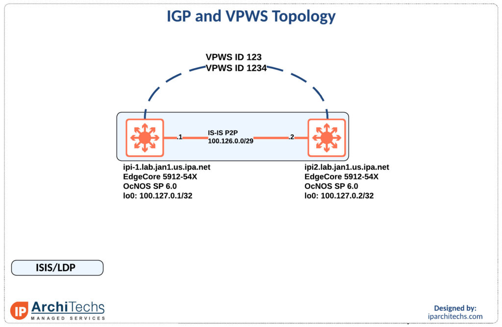
We setup a simple topology of isis and ldp to create VPWS circuits. We are going to build two circuits in this example.
ipi-1.lab.jan1.us.ipa.net#show run mpls
<<output snipped>>
mpls l2-circuit TAG-TEST 123 100.127.0.2
!
mpls l2-circuit TEST-TAG-4 1234 100.127.0.2
!
<<output snipped>>
router ldp
 router-id 100.127.0.1
 targeted-peer ipv4 100.127.0.2
  exit-targeted-peer-mode
VPWS and Attachment Circuit Topology
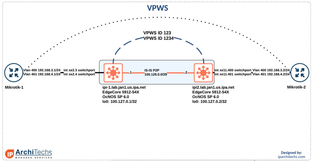
We are going to attach the circuits to the same physical ports and utilize tags to place the traffic into the correct VPWS circuit. Mikrotik-1 is double tagged and Mikrotik-2 is single tagged.
If you’ve built pseudowires on OcNOS before you might be familiar with the service-template model. However, when building VPWS circuits and utilizing the same interface this isn’t an option. You have to make a subinterface that is a switchport. This also changes the method for tag operations.
ipi-1.lab.jan1.us.ipa.net#show run interface

<<output snipped>>

interface xe2
 switchport
!
interface xe2.3 switchport
 encapsulation dot1q 3 inner-dot1q 400-499
 rewrite pop
 access-if-vpws
  mpls-l2-circuit TAG-TEST primary
!
interface xe2.4 switchport
 encapsulation dot1q 4 inner-dot1q 400-499
 rewrite pop
 access-if-vpws
  mpls-l2-circuit TEST-TAG-4 primary
!
The switchport subinterfaces are then assigned as an access interface matching specific tags. In this case outer tag 3 and inner tag 400-499. On IPI-2 we are expecting single tagged frames instead of double tagged. This is where the rewrite pop comes in. This will remove the outer tag on ingress to the PW and push it back on on egress towards Mikrotik-1.
ipi-2.lab.jan1.us.ipa.net#show run interface

<<output snipped>>

interface xe11
 speed 1g
 switchport
!
interface xe11.4 switchport
 encapsulation dot1q 401
 access-if-vpws
  mpls-l2-circuit TEST-TAG-4 primary
!
interface xe11.400 switchport
 encapsulation dot1q 400
 access-if-vpws
  mpls-l2-circuit TEST-TAG primary
!
Since the AC towards Mikrotik-2 is only expecting single tagged packets we just do a simple match on encapsulation.
Let’s do some verification. First we’ll verify that the circuits are up.
ipi-2.lab.jan1.us.ipa.net#show ldp targeted-peers
IP Address          Interface
100.127.0.1         xe48

ipi-2.lab.jan1.us.ipa.net#show ldp mpls-l2-circuit
Transport     Client     VC     VC            Local       Remote      Destination
VC ID         Binding    State  Type          VC Label    VC Label    Address
123           xe11.400   UP     Ethernet VLAN 25602       26240       100.127.0.1
1234          xe11.4     UP     Ethernet VLAN 25603       26241       100.127.0.1

ipi-2.lab.jan1.us.ipa.net#show ldp mpls-l2-circuit detail
PW ID: 123, VC state is up
Access IF: xe11.400,up,AC state is up
Session IF: xe48, state is up
Destination: 100.127.0.1, Peer LDP Ident: 100.127.0.1
Local vctype: vlan, remote vctype :vlan
Local groupid: 0, remote groupid: 0
Local label: 25602, remote label: 26240
Local MTU: 1500, Remote MTU: 1500
Local Control Word: disabled  Remote Control Word: Not-Applicable  Current use: disabled
Local Flow Label Direction: Disabled, Static: Disabled
Remote Flow Label Direction: Both , Static: Disabled
Local PW Status Capability : disabled
Remote PW Status Capability : disabled
Current PW Status TLV : disabled

PW ID: 1234, VC state is up
Access IF: xe11.4,up,AC state is up
Session IF: xe48, state is up
Destination: 100.127.0.1, Peer LDP Ident: 100.127.0.1
Local vctype: vlan, remote vctype :vlan
Local groupid: 0, remote groupid: 0
Local label: 25603, remote label: 26241
Local MTU: 1500, Remote MTU: 1500
Local Control Word: disabled  Remote Control Word: Not-Applicable  Current use: disabled
Local Flow Label Direction: Disabled, Static: Disabled
Remote Flow Label Direction: Disabled, Static: Disabled
Local PW Status Capability : disabled
Remote PW Status Capability : disabled
Current PW Status TLV : disabled
Then let’s verify that we can pass traffic.

We have successfully manipulated the tags and passed traffic end to end. We started with a double tagged packet, pop off the outer tag, placed it into a PW, spit out a single tagged packet, and had end to end reachability.
Conclusion
There are various methods and configurations to manipulate traffic. This is one of the more common examples of tag manipulation that occurs in broadband aggregation. I will explore tag manipulation with service-templates and VPLS in a later post.