 +1 (855)
 With the current state of the supply chain lead times for networking gear can be astronomical. This led consumers to look at other options for networking equipment forcing the whitebox and disaggregated networking market to become more prevalent.
With full featured operating systems like IP Infusion‘s OcNOS 6.0 and commodity hardware from Ufispace and Edgecore companies have been about to upgrade faster and further than ever before.
We’ll be looking at the ufispace 9600-32s and 9500-30xs in this deployment. This is shaping up to be a great combination for 100g and 10g density. Since both run the same operating system moving between is easy. While the bigger Qumran2c, 9600-32s, doesn’t support breakouts/10g we can aggregate and terminate 100g services here while using a small device to delivery 10g density and breakout.
We’re going to look specifically at VPLS and VPWS delivery in this deployment. Since these deployments typically complement existing deployments we’ll look at interop with a Calix e9-2 ASM 3001 deployment.
I know Calix doesn’t normally come to mind for MPLS deployments but more for FTTX or ERPS. However, they’ve been putting a lot of effort into their MPLS stack on the e9-2 ASM platform which has helped led to this testing.
We also have an Arista 7280CR3K-32P4 acting as a p-router during link failure.
IGP/LDP Setup
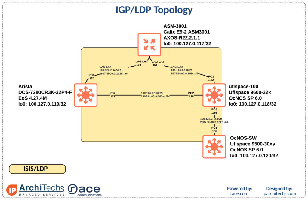
We’re going to run isis as an IGP which is typical in a service provider network. This time we’re going to run straight LDP instead of SR-MPLS, however, you can still utilize SR-MPLS with a mapping server if your topology supports it.
Let’s verify IGP/LDP and routing.
ASM3001# show isis neighbors
NEIGHBOR                                HOLD  CIRCUIT
SYSTEM ID       TYPE  INTERFACE  STATE  TIME  ID
-------------------------------------------------------
0010.0127.0118  L2    la3        UP     23    3
0010.0127.0119  L2    la4        UP     26    4

 details
NEIGHBOR                                HOLD  CIRCUIT
SYSTEM ID       TYPE  INTERFACE  STATE  TIME  ID
-------------------------------------------------------
0010.0127.0118  L2    la3	 UP	23    3
Hostname:ufispace-100
SNPA:e8c5.7a77.a655
State Changed:3214
LAN Priority:0
Restart Capable:1
Peer Restart State:1
0010.0127.0119  L2    la4	 UP	26    4
Hostname:ARISTA
SNPA:c4ca.2b66.fb6d
State Changed:3152
LAN Priority:0
Restart Capable:1
Peer Restart State:1
-------------------------------------------------------
ASM3001# show mpls ldp neighbors
LOOP INTERFACE
INDEX PEER LDP ID LOCAL LDP ID TYPE SESSION DISTMODE DETECTION TRANS ADD NAME
---------------------------------------------------------------------------------------------------------------
1 100.127.0.118:0 100.127.0.117:0 TARGETED DownstreamUnsolicited Disabled 100.127.0.119 none
2 100.127.0.118:0 100.127.0.117:0 DIRECTED DownstreamUnsolicited Disabled 100.127.0.119 la3
3 100.127.0.119:0 100.127.0.117:0 DIRECTED DownstreamUnsolicited Disabled 100.127.0.119 la4ASM3001# show ip route all
ROUTE
INDEX PREFIX NEXT HOP TYPE DISTANCE INTERFACE UPTIME
----------------------------------------------------------------------------
1 100.126.2.160/29 100.126.2.161 local 0/0 la3 0:9:47
2 100.126.2.161/32 0.0.0.0 local 0/0 la3 0:9:47
3 100.126.2.168/29 100.126.2.169 local 0/0 la4 0:9:42
4 100.126.2.169/32 0.0.0.0 local 0/0 la4 0:9:42
5 100.126.2.176/29 100.126.2.162 isis 115/20 la3 0:9:33
6 100.126.2.170 isis 115/20 la4 0:9:33
7 100.126.2.184/29 100.126.2.162 isis 115/20 la3 0:9:33
8 100.127.0.117/32 0.0.0.0 local 0/0 loopback1 0:9:53
9 100.127.0.118/32 100.126.2.162 isis 115/20 la3 0:9:33
10 100.127.0.119/32 100.126.2.170 isis 115/20 la4 0:9:33
11 100.127.0.120/32 100.126.2.162 isis 115/30 la3 0:9:33ASM3001# ping 100.127.0.120
PING 100.127.0.120 (100.127.0.120) 56(84) bytes of data.
64 bytes from 100.127.0.120: icmp_seq=1 ttl=63 time=0.778 ms
64 bytes from 100.127.0.120: icmp_seq=2 ttl=63 time=0.722 msOcNOS-SW#show clns neighbors
Total number of L1 adjacencies: 0
Total number of L2 adjacencies: 1
Total number of adjacencies: 1
Tag UNDERLAY: VRF : default
System Id Interface SNPA State Holdtime Type Protocol
ufispace-100 po1 e8c5.7a77.a657 Up 26 L2 IS-ISOcNOS-SW#show mpls ldp neighbor
IP Address Mode Intf Name Holdtime LDP-Identifier
100.126.2.185 Interface po1 15 100.127.0.118:0
fe80::eac5:7aff:fe77:a657Interface po1 15 100.127.0.118:0
100.127.0.117 Targeted po1 45 100.127.0.117:0OcNOS-SW#ping 100.127.0.117 source-ip 100.127.0.120
Press CTRL+C to exit
PING 100.127.0.117 (100.127.0.117) from 100.127.0.120 : 56(84) bytes of data.
64 bytes from 100.127.0.117: icmp_seq=1 ttl=64 time=0.811 ms
64 bytes from 100.127.0.117: icmp_seq=2 ttl=64 time=0.746 msSince we have LDP neighbors and loopback to loopback reachability we can begin to build our services.
100g VPWS
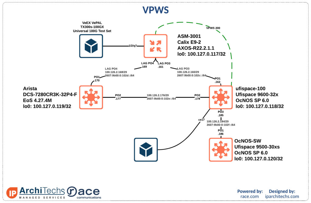
First we’ll build a VPWS service between the E9-2 and ufispace-100 to verify functionality. We’ll utilize a TX300s-100GX test set to push traffic through the service.
First lets look at the ASM configuration for the xconnect.
ASM3001# show running-config l2vpn
l2vpn 1
 pw-class PWE-1
  encapsulation mpls
   cc-type        TTL
   transport-mode vlan
  !
 !
 point2point 200
  xconnect-neighbor 100.127.0.118 pw-id 200
   pw-class  PWE-1
   pw-status enable
  !
 !
!
Below you can see the config for the interface facing the test set. This will put the traffic into the VPWS service.
ASM3001# show running-config interface ethernet 1/2/q7
interface ethernet 1/2/q7
 no shutdown
 role     uni
 arp arp-announce any
 l2transport
  point-to-point 200
 !
!
Now we can see the same on the IP infusion side.
ufispace-100#show run mpls
!
service-template TEST
 match all
!
mpls l2-circuit TEST-VPWS 200 100.127.0.117ufispace-100#show run int ce17
!
interface ce17
switchport
mtu 1986
mpls-l2-circuit TEST-VPWS service-template TEST primary
!Finally lets verify functionality. I did a verbose output of the circuit details to help see all of the details. Some important things to match are the MTU and if it’s a vlan or raw service.
IP Infusion sets the MTU on the attachment circuit while Calix is inherited from the default interface value of 2000 minus some overhead.
ufispace-100#show ldp mpls-l2-circuit detail
PW ID: 200, VC state is up
Access IF: ce17,up,AC state is up
Session IF: po1, state is up
Destination: 100.127.0.117, Peer LDP Ident: 100.127.0.117
Local vctype: vlan, remote vctype :vlan
Local groupid: 0, remote groupid: 0
Local label: 24962, remote label: 26
Local MTU: 1986, Remote MTU: 1986
Local Control Word: disabled  Remote Control Word: Not-Applicable  Current use: disabled
Local Flow Label Direction: Disabled, Static: Disabled
Remote Flow Label Direction: Disabled, Static: Disabled
Local PW Status Capability : disabled
Remote PW Status Capability : enabled
Current PW Status TLV : disabled
Local VCCV Capability:
 CC-Types: None
 CV-Types: None
Remote VCCV Capability:
 CC-Types:  Type 3
 CV-Types:
LSP pingASM3001# show l2vpn xconnect pw-id 200
l2vpn xconnect pw-id 200
XCONNECT NAME STATE
--------------------------------- ---------------
200 Up
-------------------------------------------------
VPWS Index : 2
VPN Key : 131074
% 1 entries in the table.
AC Details
-------------------------------------------------
INTERFACE VLAN STATE TYPE MTU VPWS-INDEX
------------ --------- --------------- ---------- --------- -----------
1/2/q7 NA Active Tagged 1986 2
% 1 entries in the table.
PW Details
-------------------------------------------------
PW-ID PW-STATE PW-CLASS ENCAPSULATION PROTOCOL ADMIN-STATE REDUNDANCY-STATE VPWS-INDEX
------ ----------------- --------------------- -------------- --------- ------------ ----------------- ----------
200 Up PWE-1 MPLS LDP Up NA 2
-----------------------------------------------------------------------------------------------------------------
PW-INFO LOCAL REMOTE
------------- -------------------- --------------------
Address 100.127.0.117 100.127.0.118
PW ID 200 uNknOwn
PW type Tagged uNknoWn
Label 26 24962
MTU 1986 1986
Control Word Disabled uNknOwn
Status TLV Enabled Disabled
CC Type 4 0
CV Type 2 0
Local Status (PW Status TLV): 0x6
Remote Status (PW Status TLV): 0x0
Create time: 2022-09-10 09:17:23
Last time status changed: 2022-09-10 09:30:28
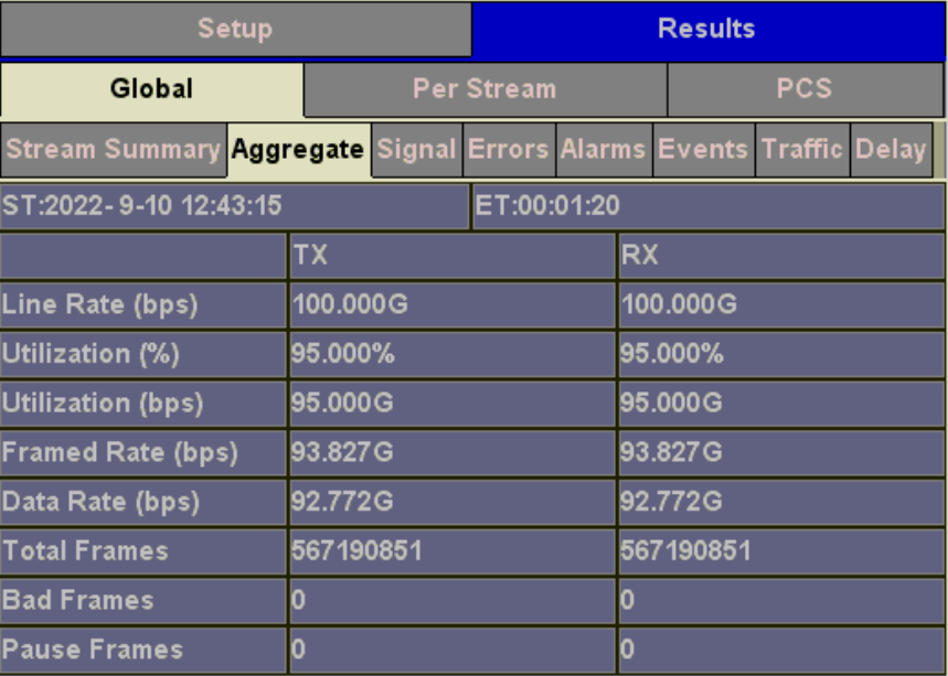
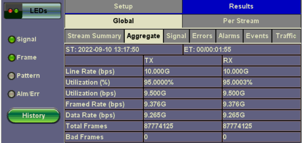
% 1 entries in the table.Finally, we can see 95g of traffic across the circuit with the test set.
10g VPLS
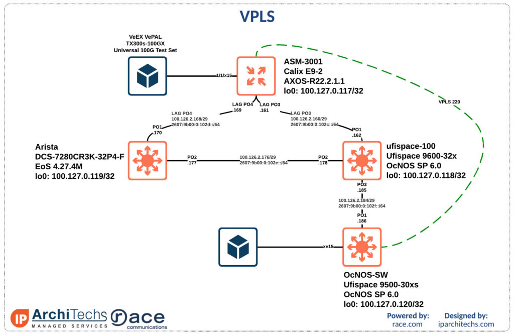
Next we will look at a 10g VPLS service delivered off the extension switch. We already saw end to end reachability in the IGP setup so we will start with configuration.
On the ASM you build a bridge domain and tie it to a virtual forwarding instance.
ASM3001# show running-config l2vpn
l2vpn 1
 pw-class vlan-pwe
  encapsulation mpls
   cc-type        TTL
   transport-mode vlan
  !
 !
Then we define the neighbor or neighbors in the VPLS.
ASM3001# show running-config l2vpn bridge-domain
l2vpn 1
 bridge-domain 220
  mtu 9086
  vfi 220
   neighbor 100.127.0.120 pw-id 220
    pw-class vlan-pwe
   !
  !
 !
!
Again, we tie the interface facing the test kit into the bridge-domain. This will put the traffic into the VPLS instance.
ASM3001# show running-config interface ethernet 1/1/x15
interface ethernet 1/1/x15
 no shutdown
 role     uni
 arp arp-announce any
 l2transport
  rewrite-ingress tag add dot1q 220
  !
  bridge-domain 220
  !
 !
!
Then we build the same on IP Infusion.
OcNOS-SW#show run vpls
!
mpls vpls TEST-VPLS 220
 signaling ldp
  vpls-type vlan
  vpls-peer 100.127.0.117
  exit-signaling
 exit-vpls
!
Here we also have to define the peers for targeted hellos in LDP.
OcNOS-SW#show run ldp
!
router ldp
 router-id 100.127.0.120
 graceful-restart full
 targeted-peer ipv4 100.127.0.117
  exit-targeted-peer-mode
 transport-address ipv4 100.127.0.120
!
Finally, we attached the a port to the service and plug in the test kit.
OcNOS-SW#show run int xe15
!
interface xe15
 switchport
 mtu 9086
 mpls-vpls TEST-VPLS service-template TEST
  exit-if-vpls
!
Again, we will look at the verbose output and pay attention to MTU and VPLS type, vlan in this case.
OcNOS-SW#show mpls vpls detail
Virtual Private LAN Service Instance: TEST-VPLS, ID: 220
 SIG-Protocol: LDP
 Attachment-Circuit :UP
 Learning: Enabled
 Control-Word: Disabled
 Flow Label Status: Disabled, Direction: None, Static: No
 Group ID: 0, VPLS Type: Ethernet VLAN, Configured MTU: 9086
 Description: none
 service-tpid: dot1.q
 Operating mode: Tagged
 Svlan Id: 0
 Svlan Tpid: 8100
 Configured interfaces:
  Interface: xe15
 Service-template : TEST
  Match criteria : Accept all

 Mesh Peers:
100.127.0.117 (Up)ASM3001# show l2vpn bridge-domain bd-name 220
l2vpn bridge-domain bd-name 220
BRIDGE DOMAIN NAME STATE
--------------------------------- ---------------
220 Up
-------------------------------------------------
VPLS Index : 3
VPN Key : 65539
MTU : 9086
MAC Learning : ENABLE
MAC Aging Time : 300
MAC Limit Max : 1024
MAC Action : FLOOD
AD Type : NONE
SIG type : NONE
Transport Mode : ETHERNET TAGGED
Control Word : DISABLE
Route Distinguisher: 0x0000000000000000(NULL)
VPLS ID : 0x0000000000000000(DEFAULT)
VE ID : 0
VE Range : 8
% 1 entries in the table.
AC Details
------------ --------------- ---------- ------------ ---------------
DESCRIPTION STATE TYPE VPLS INDEX SPLIT HORIZON
------------ --------------- ---------- ------------ ---------------
1.x15 Active Ethernet 3 Disabled
% 1 entries in the table.
PW Details
PW-ID STATE PW-Class ENCAPSULATION VPLS-INDEX ADMIN-STATE
--------------- ----------- --------------------- -------------- ---------- ------------
220 Up vlan-pwe MPLS 3 Up
------------------------------------------------------------------------------------
------------- -------------------- --------------------
PW LOCAL REMOTE
------------- -------------------- --------------------
Address 100.127.0.117 100.127.0.120
PW ID 220 uNknOwn
PW type Tagged uNknoWn
Label 34 24961
MTU 9086 9086
Control Word Disabled uNknOwn
Status TLV Enabled Disabled
CC Type 4 0
CV Type 2 0
Create time: 2022-09-10 09:55:06
Last time status changed: 2022-09-10 09:58:56
% 1 entries in the table.Finally, we can see all of the traffic on the test set across the circuit.
Conclusion
Disaggregated networking provides an alternative to traditional vendors and these are real world examples of service deployment for service providers. A special thanks to Sorin Esanu and Race Communications for organizing this test environment as a proof of concept for their deployment.