 +1 (855) 645-7684
VPLS is a pretty common technology in ISPs to either sell layer 2 services or backhaul traffic to a centralized aggregation point to conserve IPv4 space; check out more on that here.
How can I take advantage of segment routing but still deliver the same services? We already looked at how to setup the label switched paths utilizing IP Infusion as a segment routing mapping server in this interop post. Now let’s see how we can deliver a VPLS service over this with mikrotik as a provider edge router.
Delivering a service with a L2VPN
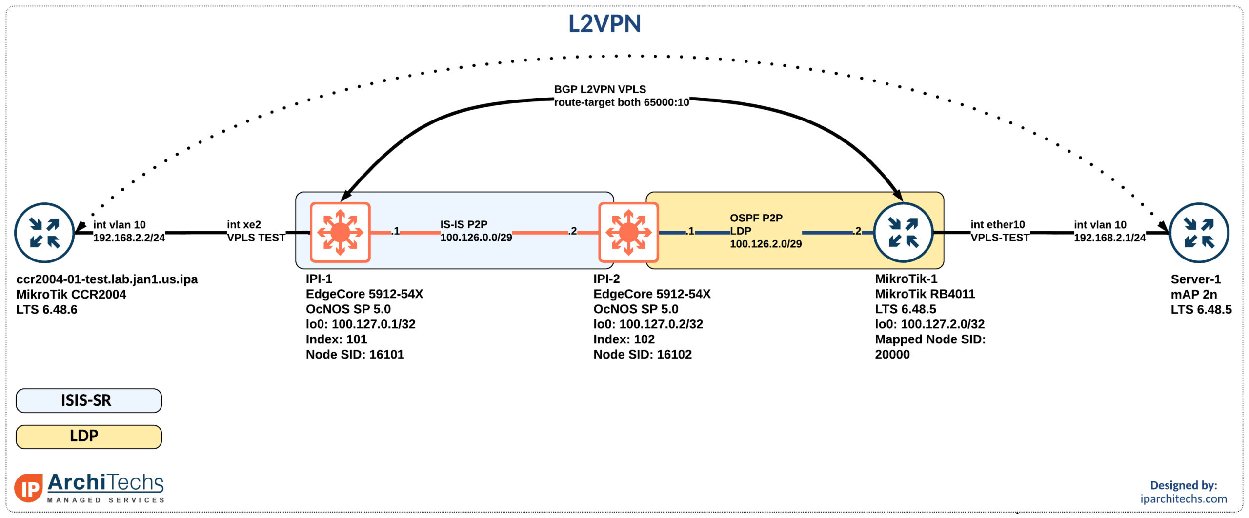
After setting up the IGP and label distribution between the PEs we will start building the L2VPN.
Why a BGP signaled VPLS session instead of LDP signaled VPLS?
In the segment-routing domain there is no LDP running. However, some vendors support static pseudowires or other methods to bring up a targeted LDP session for VPLS. I did some basic testing here couldn’t easily identify the right combination of knobs to make this work. Don’t worry; I’ll come back to it.
BGP signaled VPLS is a standards based technology that both vendors support.
First thing we need to do after having loopback reachability is to build the BGP sessions.
ipi-1.lab.jan1.us.ipa.net:

router bgp 65000
 neighbor 100.127.2.0 remote-as 65000
 neighbor 100.127.2.0 update-source lo
 !
 address-family l2vpn vpls
 neighbor 100.127.2.0 activate
!
MikroTik-1:
/routing bgp peer
add address-families=l2vpn name=OCNOS1 nexthop-choice=force-self \
remote-address=100.127.0.1 remote-as=65000 update-source=Lo0After establishing the BGP peering we need to build the vpls instance.
ipi-1.lab.jan1.us.ipa.net:

mpls vpls TEST 10
 signaling bgp
  ve-id 10
  exit-signaling
 exit-vpls
!
MikroTik-1:
/interface vpls bgp-vpls
add bridge=VPLS-TEST export-route-targets=65000:10 import-route-targets=\
65000:10 name=TEST route-distinguisher=100.127.2.0:10 site-id=2 \
use-control-word=noOn OcNOS the route-target and route distinguisher is automatically derived from the vpls instance creation. While you explicitly set it on MikroTik.
ipi-1.lab.jan1.us.ipa.net# show mpls vpls TEST
Virtual Private LAN Service Instance: TEST, ID: 10
 SIG-Protocol: BGP
  Route-Distinguisher :65000:10
  Route-Target :65000:10
  VE-ID :10
The site-id (Tik) or VE-ID (OcNOS) are the vpls endpoint identifiers which uniquely identify each PE.
The final step before we can start to test is to setup the attachment circuit. On OcNOS we will have to setup a service template to pair with the vpls instance on attachment circuit. Then you can assign the vpls instance and the service template to a switchport. We will match vlan tag 10 on our service template. Anything coming in with dot1q 10 from the CCR2004 will enter the VPLS tunnel.
ipi-1.lab.jan1.us.ipa.net:

service-template TEST
 match outer-vlan 10
!
interface xe2
 switchport
 mpls-vpls TEST service-template TEST
  exit-if-vpls
!
On the MikroTik side we need to setup a bridge for the autocreation of the tunnels and assign appropriate interfaces to it. Again, we will match on dot1q 10.
MikroTik-1:

/interface bridge
add name=Lo0
add name=LoVOICE
add mtu=1500 name=VPLS-TEST protocol-mode=none

/interface bridge port
add bridge=VPLS-TEST interface=ether10 pvid=10

/interface bridge vlan
add bridge=VPLS-TEST tagged=VPLS-TEST untagged=vlan10,ether10 vlan-ids=10
Finally, we can do testing and verification. We want to look for the mesh peer which is the autodiscovered PE also in this vpls instance.
ipi-1.lab.jan1.us.ipa.net#show mpls vpls TEST
Virtual Private LAN Service Instance: TEST, ID: 10
 SIG-Protocol: BGP
  Route-Distinguisher :65000:10
  Route-Target :65000:10
  VE-ID :10
 Attachment-Circuit :UP
 Learning: Enabled
 Control-Word: Disabled
 Group ID: 0, Configured MTU: 1500
 Description: none
 service-tpid: dot1.q
 Operating mode: Raw
 Configured interfaces:
  Interface: xe2
 Service-template : TEST
  Match criteria : 10

 Mesh Peers:
   100.127.2.0 (Up)
Then we want to make sure we are learning mac-addresses. As you can see the MACs not learned from the attached device are learned from the BGP peer at 100.127.2.0.
ipi-1.lab.jan1.us.ipa.net#show mpls vpls mac-address
VPLS-ID     MAC address       Learned from   Vlan-Id          Peer address   Tim
e-out
10          027b.6866.7831    xe48           -                100.127.2.0    300

10          488f.5a00.4f87    xe2            10               -              300


10          4c5e.0c6f.4476    xe48           -                100.127.2.0    300
Next we can test reachability. I did have a strange issue where if the AC went down on the MikroTik-1 the mesh wouldn’t form on reattachment. This was resolvable with the following command on IPI-1: clear bgp 100.127.2.0 l2vpn vpls
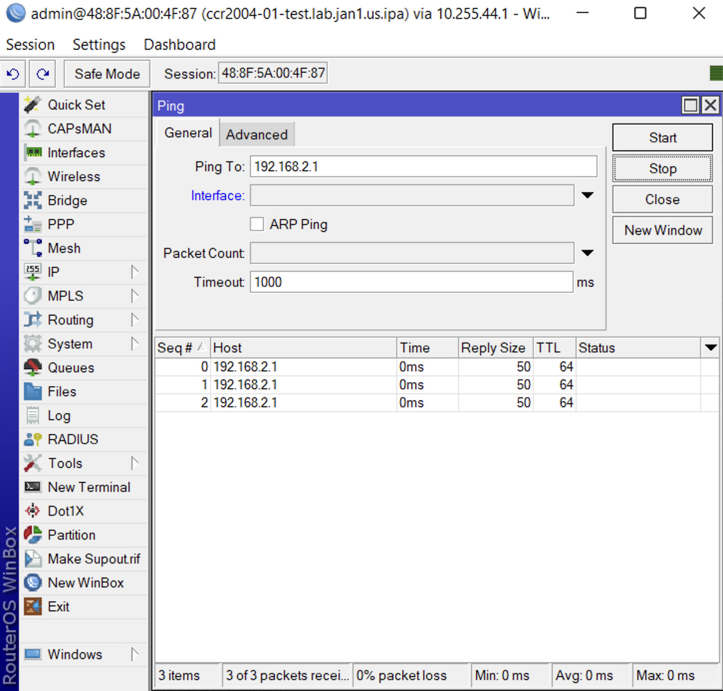

I’ll be doing more testing on interop here. Let us know in the comments what you’d like to see next.