 +1 (855)
 Hey guys, today we’ll be taking a look at what are the main reasons that MPLS – and in particular VPLS – is a useful technology tool to get traffic from point A to point Z. There’s really 2 major use cases that I deal with regularly: IPv4 conservation and L2VPN.
Why am I talking about VPLS specifically? Well, mostly because many times I end up working with Mikrotik routers, which only support VPLS. What is VPLS? It stands for Virtual Private Line Service, and it’s a way to deliver layer 2 services over a layer 3 network. Said another way, it connects a single broadcast domain to multiple endpoints across a routed network. I’ll discuss why MPLS is better for you and your network than switching/bridging in part 2 of this series – for now just know that MPLS/VPLS will allow you to offer enhanced services without the risks of extending layer 2 (I’ll talk more about that below, and why that’s bad in part 2, also).
Use case 1: IPv4 Conservation
OK, so let’s visualize the problem with IP conservation on a small /24 allocation.
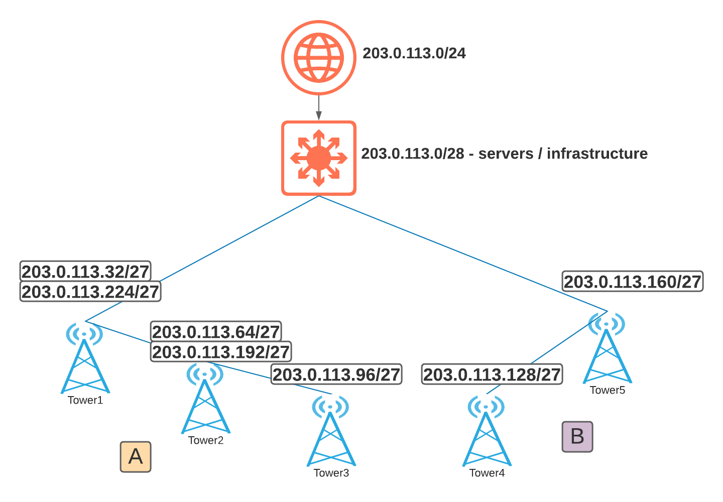
If you’re like most other service providers, you have a limited capacity of IPv4 and constantly using subnetting to carve out IP space for various locations. Inevitably, you end up needing a bigger network somewhere (like A) and in other places you’ve allocated too many IPs and they’re going wasted and unused (like B). Not to mention, with subnetting we’re forced to burn a network ID and broadcast each time we pull out the network scalpel – ouch!
As you can see, in this network, subnetting has resulted in 16 IPs used for IDs and subnets, 8 more for gateways, and over in area B let’s say there’s 37 unassigned IPs – that’s 60 IPs out of 254 that customers can’t use, almost 25% of this expensive revenue generating resource is tied up!
Here’s a solution based on MPLS/VPLS that efficiently leverages the entire /24 allocation:
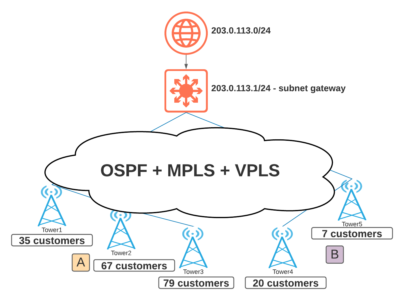
Now we’re only using 1 network ID, 1 broadcast, and 1 gateway for our /24. The entire rest of the allocation can be delivered to any endpoint that’s connected the MPLS cloud – leaving 253 addresses available for customer assignments! And growth can happen at any tower – we no longer have to care which customers are on which tower, and how much IP space is available at the tower layer.
Compared to the above scenario, our IP allocation overhead went down from 25% to just over 1%! Now that’s efficient use of IPv4 space.

Use case 2: L2VPN
Connecting multiple offices across a service provider network can often be a very lucrative way to offer transparent LAN service to customers. The reason we call it transparent is because it allows whatever customer traffic is input in one end of the network to be seen at another end of the network. In a typical routed network, BUM traffic (which I’ll cover more in part 2) gets isolated at layer 3, routed boundaries. With VPLS, your network gets the full benefits of the layer 3 boundaries, and your customer gets the connectivity benefits of being connected layer 2!
Some of the more common customers looking for a L2VPN service include government, energy and banks. But really, any customer who’d like to connect the same subnet at several different physical locations that are served by different equipment across your network are a great candidates. Sometimes they’d like to pass their own VLAN traffic, other times they need multicast for a video conferencing application, or even something as simple as a small network with only 1 DHCP server / firewall / internet gateway and they want to force all traffic through that central point. Regardless of the reason, this premium service can bring in great revenue.
Can’t I just provide L2 service by extending a VLAN? Absolutely, you can. Should I just extend my bridged/switched network to provide this service? NO! You should absolutely avoid this as much as possible! As we’ll see in part 2, isolating fault domains and adding L3 boundaries are key to protecting your network from bad days.
Let’s see an example:
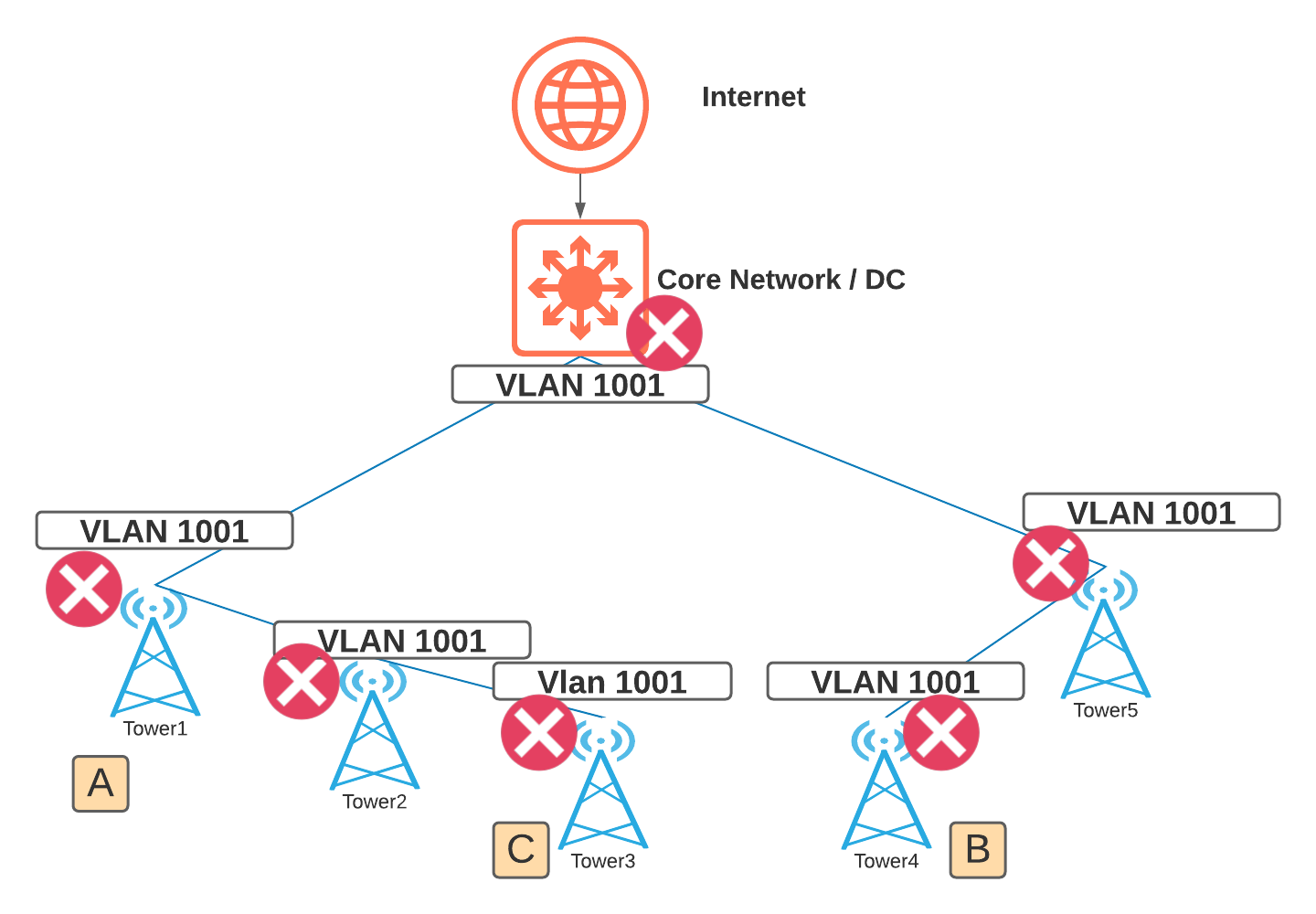
Here, we’ve extended the network using bridging and switching (L2) constructs to connect customer locations A B and C. When we have a bad day on this network, the scope of our network meltdown includes the entirety of ALL the gear and ALL our customers. Ouch!
Whether it’s a customer introduced loop, infected customer device, or a customer host spewing garbage onto to their network, there’s no protection between the customer edge (CE) and provider edge (PE) and no boundaries to stop that bad traffic.
Fortunately, there’s a better way:
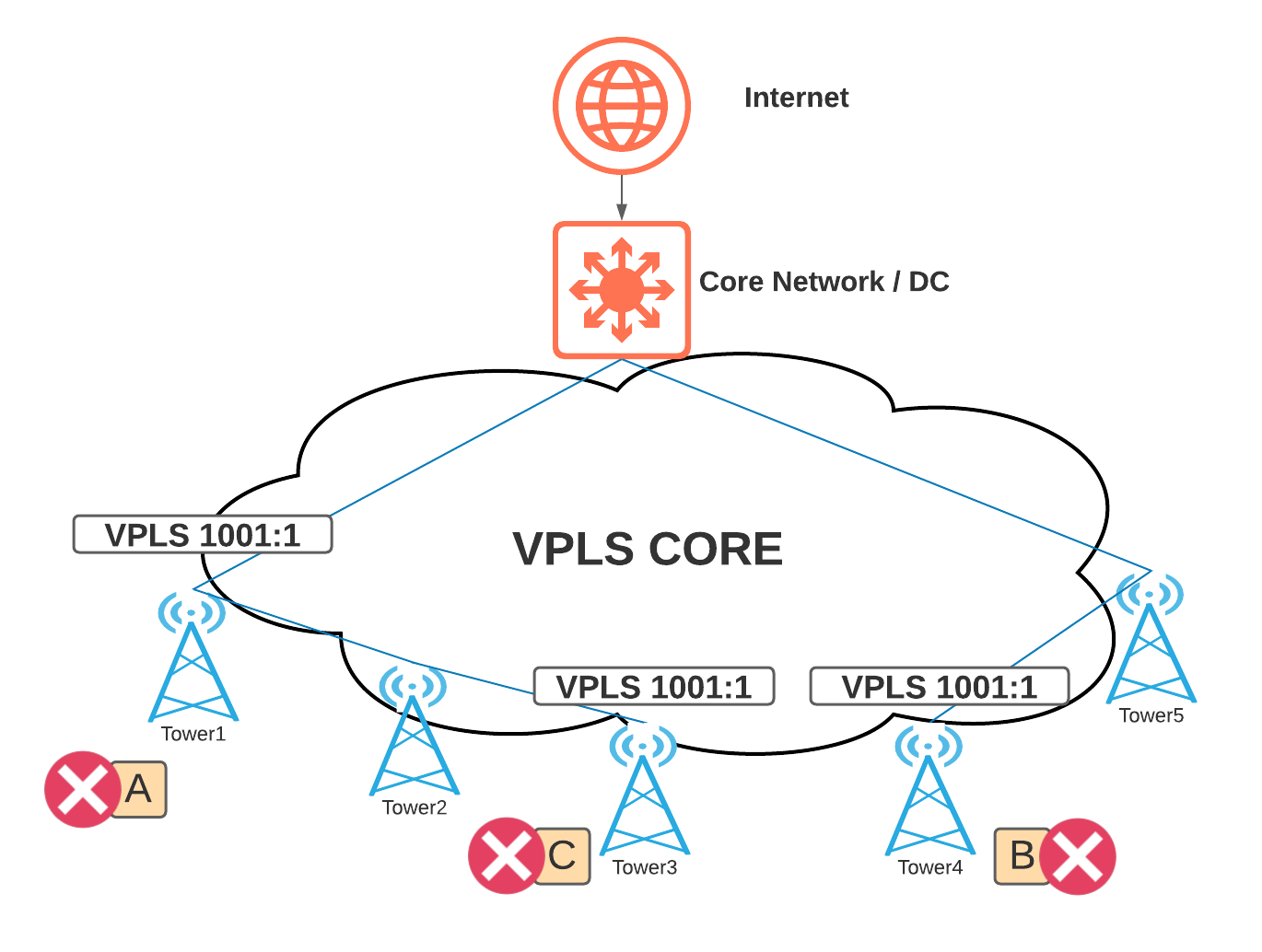
With MPLS/VPLS, you can see that the scope of our outage is isolated to the customer edge (the port handoff to A, B, and C), or at worst only the VPLS router endpoints, depending on the gear, QoS policies, and configuration. Now, a bad day on the customer’s network isn’t necessarily a bad day for our service provider network.
I hope you enjoyed this article and keep an eye out for part 2 where I’ll talk more in depth about L2 (bridging/switching) vs L3 (routing) and why MPLS/VPLS is referred to as layer 2.5.