 +1 (855)
 If you read part 2 of this series and came out wondering this is great but:
How do I connect to the internet?
Does this breakdown once I need to have connections?
What else do I have to do to manage state?
We’ll set out to answer these questions and show how it works. There are some dependancies such as your provider supporting customer BGP TE communities as laid out in part 3.
This seems to be the elusive grail in enterprise networking that everyone wants but is unsure of where to start. Hopefully, a few of those questions have been answered throughout this series but be sure to understand what you’re getting into and that your team can support it before and after you leave.
The overall topology
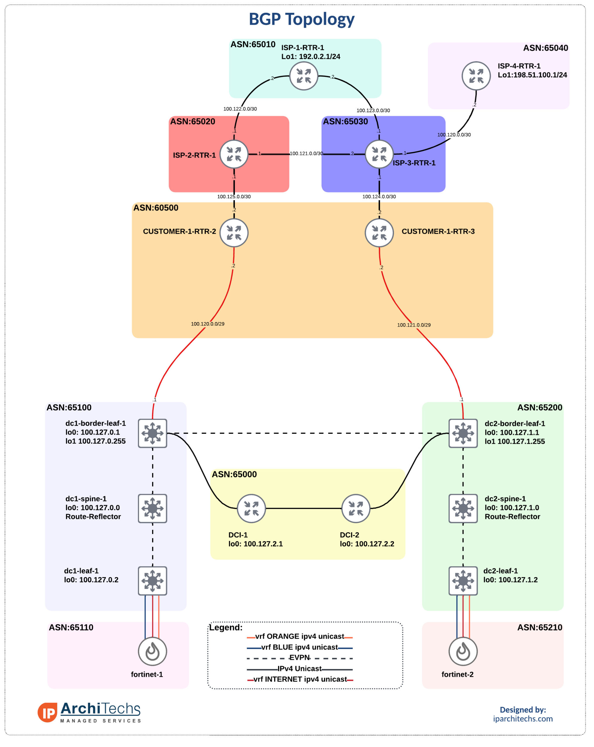
We’ve got data center 1 (DC1) and data center 2 (DC2). They each have a connection to an internal router in ASN 60500. A lot of networks I come across have dedicated routers coming out of the DC to terminate internet connections and support full tables. These router usually only pass a default internally. I don’t have the full tables but instead copy the topology and pass a default into the dc1 and dc2 borders.
We’ll be looking at DC1 to keep the amount of variables and options down. We set the community on the default route received from the customer-1-rtr2 to utilize later on advertisements to the FW. This is important for state management.
dc1-border-leaf-1# show ip bgp vrf INTERNET
BGP routing table information for VRF INTERNET, address family IPv4 Unicast
BGP table version is 232, Local Router ID is 10.150.0.0
Status: s-suppressed, x-deleted, S-stale, d-dampened, h-history, *-valid, >-best
Path type: i-internal, e-external, c-confed, l-local, a-aggregate, r-redist, I-i
njected
Origin codes: i - IGP, e - EGP, ? - incomplete, | - multipath, & - backup, 2 - b
est2
dc1-border-leaf-1# show ip bgp vrf INTERNET 0.0.0.0/0
BGP routing table information for VRF INTERNET, address family IPv4 Unicast
BGP routing table entry for 0.0.0.0/0, version 223
Paths: (2 available, best #2)
Flags: (0x80c001a) (high32 0x000020) on xmit-list, is in urib, is best urib rout
e, is in HW, exported
  vpn: version 431, (0x00000000100002) on xmit-list

  Path type: external, path is valid, not best reason: AS Path, no labeled nexth
op
             Imported from 100.127.1.1:5:[5]:[0]:[0]:[0]:[0.0.0.0]/224
  AS-Path: 65200 60500 65030 , path sourced external to AS
    100.127.1.1 (metric 0) from 100.127.1.255 (100.127.1.1)
      Origin IGP, MED not set, localpref 100, weight 0
      Received label 3003002
      Community: 65200:3002
      Extcommunity: RT:65100:3003002 ENCAP:8 Router MAC:5004.0000.1b08

  Advertised path-id 1, VPN AF advertised path-id 1
  Path type: external, path is valid, is best path, no labeled nexthop, in rib
  AS-Path: 60500 65020 , path sourced external to AS
    100.120.0.2 (metric 0) from 100.120.0.2 (100.127.0.1)
      Origin IGP, MED not set, localpref 100, weight 0
      Community: 65100:3002
      Extcommunity: RT:65100:3003002

  VRF advertise information:
  Path-id 1 not advertised to any peer

  VPN AF advertise information:
  Path-id 1 not advertised to any peer

dc1-border-leaf-1# show run | section bgp

<<SNIP>>

  vrf INTERNET
    address-family ipv4 unicast
      redistribute direct route-map RM-CON-INTERNET
    neighbor 100.120.0.2
      remote-as 60500
      address-family ipv4 unicast
        as-override
        send-community
        route-map INET-IN in

dc1-border-leaf-1# show run rpm

<<SNIP>>

route-map INET-IN permit 10
  set community 65100:3002

dc1-border-leaf-1# show ip bgp neighbors 100.120.0.2 advertised-routes vrf INTERNET

Peer 100.120.0.2 routes for address family IPv4 Unicast:
BGP table version is 232, Local Router ID is 10.150.0.0
Status: s-suppressed, x-deleted, S-stale, d-dampened, h-history, *-valid, >-best
Path type: i-internal, e-external, c-confed, l-local, a-aggregate, r-redist, I-i
njected
Origin codes: i - IGP, e - EGP, ? - incomplete, | - multipath, & - backup, 2 - b
est2

   Network            Next Hop            Metric     LocPrf     Weight Path
*>i10.0.0.0/32        100.127.0.2                       100          0 65110 651
10 ?
*>i10.0.0.1/32        100.127.0.2                       120          0 65110 651
10 65200 ?
*>i10.100.0.0/32      100.127.0.2                       100          0 65110 651
10 ?
*>r10.150.0.0/32      0.0.0.0                  0        100      32768 ?
*>e10.151.0.0/32      100.127.1.1              0                     0 65200 ?
*>e100.127.0.2/32     100.127.1.1              0                     0 65200 605
00 i
*>i192.168.1.0/24     100.127.0.2                       100          0 65110 651
10 ?
*>i192.168.2.0/24     100.127.0.2                       120          0 65110 651
10 65200 ?
*>i192.168.10.0/24    100.127.0.2                       100          0 65110 651
10 ?
*>i192.168.20.0/24    100.127.0.2                       120          0 65110 651
10 65200 ?
So, we’ve got our default route in and advertise all our internal subnets 192.168.xx.0/24 towards the edge. When xx starts with 1 it’s from DC1 and when it starts with 2 it’s from DC2.
We utilize the provider communities referenced in part 3 to set dc1 to prefer ISP-2 and dc2 to prefer ISP-3. Pay close attention to the local preference on ISP2 in the output below.
CUSTOMER-1-RTR-2#show run

 <<SNIP>>

router bgp 60500
 bgp router-id 100.127.0.1
 bgp log-neighbor-changes
 neighbor 100.125.0.1 remote-as 65020
 neighbor 100.125.0.1 send-community
 neighbor 100.125.0.1 route-map FROM-INET in
 neighbor 100.125.0.1 route-map TO-INET out

ip prefix-list DC1-PRIMARY seq 5 permit 192.168.1.0/24
ip prefix-list DC1-PRIMARY seq 10 permit 192.168.10.0/24
!
ip prefix-list DC2-PRIMARY seq 5 permit 192.168.2.0/24
ip prefix-list DC2-PRIMARY seq 10 permit 192.168.20.0/24
!
ip prefix-list DEFAULT seq 5 permit 0.0.0.0/0
!
ip prefix-list LOOPBACK seq 5 permit 100.127.0.1/32
!
route-map TO-INET permit 10
 match ip address prefix-list DC1-PRIMARY
 set community 65020:120
!
route-map TO-INET permit 20
 match ip address prefix-list DC2-PRIMARY
 set community 65020:80
!ISP-2-RTR-1#show ip bgp
BGP table version is 400, local router ID is 100.127.2.1
Status codes: s suppressed, d damped, h history, * valid, > best, i - internal,
r RIB-failure, S Stale, m multipath, b backup-path, f RT-Filter,
x best-external, a additional-path, c RIB-compressed,
Origin codes: i - IGP, e - EGP, ? - incomplete
RPKI validation codes: V valid, I invalid, N Not found
Network Next Hop Metric LocPrf Weight Path
0.0.0.0 0.0.0.0 0 i
*> 100.127.2.1/32 0.0.0.0 0 32768 i
* 100.127.3.1/32 100.122.0.2 0 65010 65030 i
*> 100.121.0.2 0 0 65030 i
* 192.0.2.0 100.121.0.2 0 65030 65010 i
*> 100.122.0.2 0 0 65010 i
*> 192.168.1.0 100.125.0.2 120 0 60500 65100 65110 65110 ?
* 192.168.2.0 100.125.0.2 80 0 60500 65100 65110 65110 65200 ?
* 100.1 Network Next Hop Metric LocPrf Weight Path
*> 192.168.10.0 100.125.0.2 120 0 60500 65100 65110 65110 ?
* 192.168.20.0 100.125.0.2 80 0 60500 65100 65110 65110 65200 ?
* 100.122.0.2 0 65010 65030 60500 65200 65210 65210 ?
*> 100.121.0.2 0 65030 60500 65200 65210 65210 ?
* 198.51.100.0 100.122.0.2 0 65010 65030 65040 i
*> 100.121.0.2 0 65030 65040 i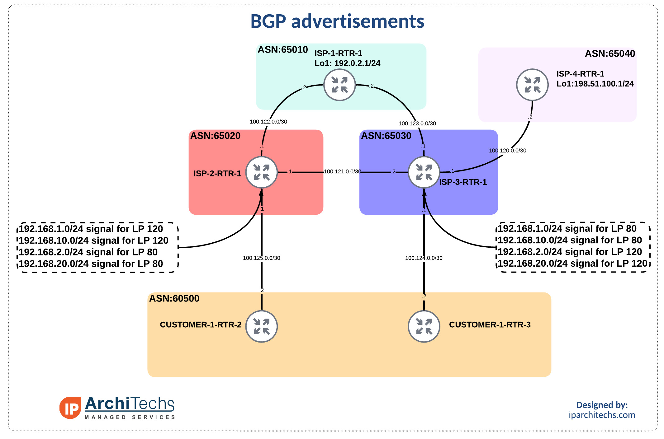

Normal conditions
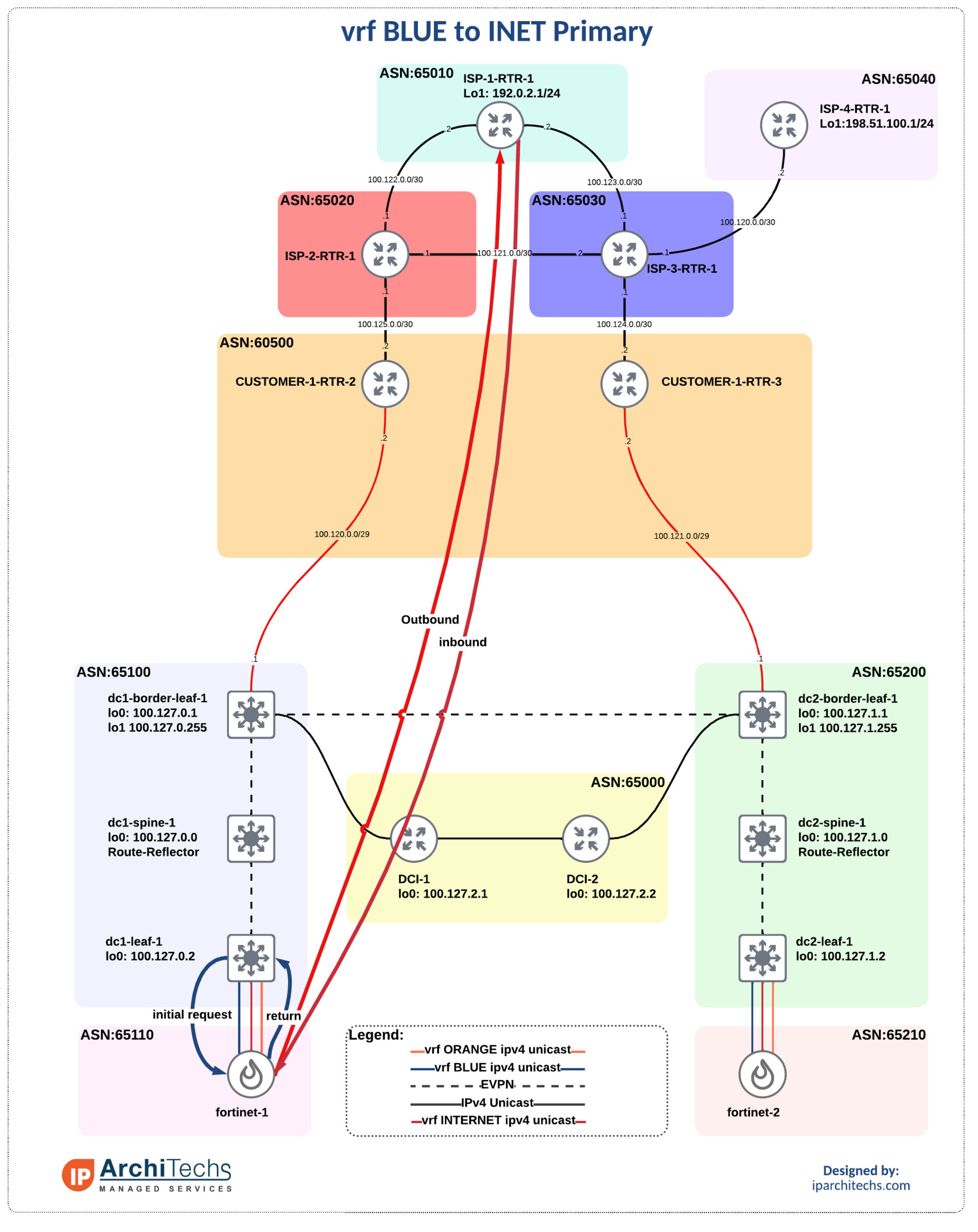
There is nothing fancy to see here, this generally speaking, just works provided the prefixes were setup to utilize their primary DC for internet connections taking advantage of customer BGP TE communities. If this is not done the WILL be a state problem. Let’s examine the path vrf BLUE takes. This will be used throughout for our reference.
vrf-BLUE-1#show ip int bri
Interface                  IP-Address      OK? Method Status                Protocol
GigabitEthernet0/0         192.168.1.2     YES manual up                    up

vrf-BLUE-1#ping 192.0.2.1
Type escape sequence to abort.
Sending 5, 100-byte ICMP Echos to 192.0.2.1, timeout is 2 seconds:
!!!!!
Success rate is 100 percent (5/5), round-trip min/avg/max = 8/9/11 ms
vrf-BLUE-1#traceroute 192.0.2.1
Type escape sequence to abort.
Tracing the route to 192.0.2.1
VRF info: (vrf in name/id, vrf out name/id)
  1 192.168.1.1 4 msec 1 msec 1 msec
  2 172.16.0.1 2 msec 3 msec 2 msec
  3 172.16.0.10 2 msec 3 msec 2 msec
  4 10.150.0.0 7 msec 7 msec 6 msec
  5 100.120.0.2 10 msec 12 msec 11 msec
  6 100.125.0.1 8 msec 9 msec 13 msec
  7 100.122.0.2 9 msec *  10 msec
FW failure
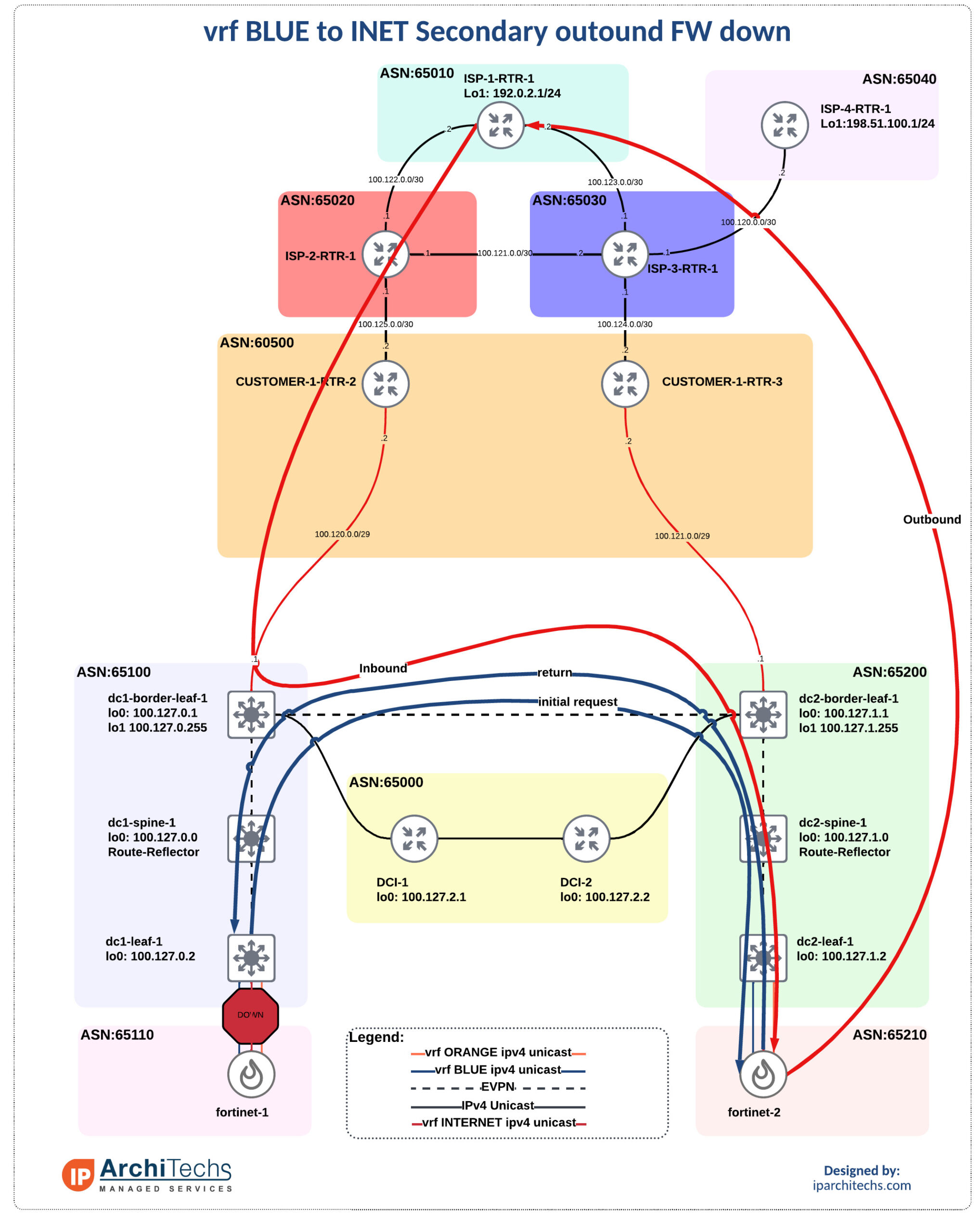
Next we’ll see what happens when the firewall in dc1 fails due to either expected or unexpected reasons.
Upon the failure all of the routes will be relearned and advertised through dc2. This is explained in detail in part 2 of this series so I will not go into details here. We will look at the final path and failure times though. Remember this lab is not running any optimizations to speed up convergence throughout the system.
vrf-BLUE-1#ping 192.0.2.1 repeat 10000
Type escape sequence to abort.
Sending 10000, 100-byte ICMP Echos to 192.0.2.1, timeout is 2 seconds:
!!!!!!!!!!!!!!!!!!!!!!!!!!!!!!!!!!!!!!!!!!!!!!!!!!!!!!!!!!!!!!!!!!!!!!
!!!!!!!!!!!!!!!!!!!!!!!!!!!!!!!!!!!!!!!!!!!!!!!!!!!!!!!!!!!!!!!!!!!!!!
!!!!!!!!!!!!!!!!!!!!!!!!!!!!!!!!!!!!!!!!!!!!!!!!!!!!!!!!!!!!!!!!!!!!!!
!!!!!!!!!!!!!!!!!!!!!!!!!!!!!!!!!!!!!!!!!!!!!!!!!!!!!!!!!!!!!!!!!!!!!!
!!!!!!!!!!!!!!!!!!!!!!!!!!!!!!!!!!!!!!!!!!!!!!!!!!!!!!!!!!!!!!!!!!!!!!
!!!!!!!!!!!!!!!!!!!!!!!!!!!!!!!!!!!!!!!!!!!!!!!!!!!!!!!!!!!!!!!!!!!!!!
!!!!!!!!!!!!!!!!!!!!!!!!!!!!!!!!!!!!!!!!!!!!!!!!!!!!!!!!!!!!!!!!!!!!!!
!!!!!!!!!!!!!!UUUUU.UU.UU.UU..............!!!!!!!!!!!!!!!!!!!!!!!!!!!!

vrf-BLUE-1#traceroute 192.0.2.1
Type escape sequence to abort.
Tracing the route to 192.0.2.1
VRF info: (vrf in name/id, vrf out name/id)
  1 192.168.1.1 2 msec 1 msec 1 msec
  2 10.0.0.0 7 msec 5 msec 6 msec
  3 10.0.0.1 10 msec 8 msec 9 msec
  4 172.16.1.2 15 msec 16 msec 15 msec
  5 172.16.1.1 17 msec 16 msec 17 msec
  6 172.16.1.10 18 msec 17 msec 18 msec
  7 10.151.0.0 22 msec 24 msec 21 msec
  8 100.121.0.2 24 msec 23 msec 24 msec
  9 100.124.0.1 24 msec 24 msec 22 msec
 10 100.123.0.2 22 msec *  29 msec
The UU and . are the point when I shut down the internet peering between dc1-leaf-1 and fortinet-1. This forced a routing change and sent the traffic over to fortinet-2 following the path seen above. You can also see the 3 additional hops due to traversing fortinet-2 instead of fortinet-1.
The return path from the internet being through customer-1-rtr-2 is due to the provider communities used earlier ensure 192.168.1.0/24 bound traffic returns in this dc to avoid a state problem during normal operations.
I’m sure with the right tooling this could be resolved but it would take an automated action or so much complexity it isn’t worth maintaining. The increased latency is probably worth the operational simplicity.
Internet failure

This failure is a little more straight forward as the outbound and return path are symmetric not only from a FW policy perspective but also from an overall perspective. We make use of the communities set on the internet advertisements to enable this failure.
Without marking the default route with an attribute to act on we wouldn’t be able to differentiate on the fortinets if the upstream internet was down which would introduce that state problem. To solve this we only send the default route from the DC that the fortinet is in.
dc1-leaf-1# show run bgp

<<SNIP>>

router bgp 65100

<<SNIP>>

  vrf INTERNET
    address-family ipv4 unicast
      redistribute direct route-map RM-CON-INTERNET
    neighbor 172.16.0.9
      remote-as 65110
      address-family ipv4 unicast
        send-community
        route-map INET-FROM-FW in
        route-map INET-TO-FW out

dc1-leaf-1# show run rpm

!Command: show running-config rpm
!Running configuration last done at: Sun Jul 24 13:16:59 2022
!Time: Sun Jul 24 13:23:46 2022

version 9.3(3) Bios:version
ip prefix-list DEFAULT seq 10 permit 0.0.0.0/0
ip community-list standard DC1-BLUE-CL seq 10 permit 65100:3000
ip community-list standard DC1-INET seq 10 permit 65100:3002
ip community-list standard DC1-ORANGE-CL seq 10 permit 65100:3001
ip community-list standard DC2-BLUE-CL seq 10 permit 65200:3000
ip community-list standard DC2-INET seq 10 permit 65200:3002
ip community-list standard DC2-ORANGE-CL seq 10 permit 65200:3001
route-map BLUE-TO-FW-IN permit 5
  match ip address prefix-list DEFAULT
route-map BLUE-TO-FW-IN permit 10
  match community DC1-ORANGE-CL
route-map BLUE-TO-FW-IN permit 20
  match community DC2-ORANGE-CL
  set local-preference 120
route-map BLUE-TO-FW-OUT permit 10
  match community DC1-BLUE-CL DC2-BLUE-CL
route-map INET-FROM-FW permit 10
  match community DC2-ORANGE-CL DC2-BLUE-CL
  set local-preference 120
route-map INET-FROM-FW permit 20
  match community DC1-ORANGE-CL DC1-BLUE-CL
route-map INET-TO-FW permit 10
  match community DC1-INET
route-map ORANGE-TO-FW-IN permit 5
  match ip address prefix-list DEFAULT
route-map ORANGE-TO-FW-IN permit 10
  match community DC1-BLUE-CL
route-map ORANGE-TO-FW-IN permit 20
  match community DC2-BLUE-CL DC2-ORANGE-CL
  set local-preference 80
route-map ORANGE-TO-FW-OUT permit 10
  match community DC1-ORANGE-CL DC2-ORANGE-CL
route-map RM-CON-BLUE permit 10
  match tag 3000
  set community 65100:3000
route-map RM-CON-INTERNET permit 10
  match tag 3002
  set community 65100:3002
route-map RM-CON-ORANGE permit 10
  match tag 3001
  set community 65100:3001
The additional route-map for inbound routes, INET-FROM-FW, is also to help maintain state. If we did not force this action to occur then under normal operations the traffic inbound from isp-2 to dc2 would go back to fortinet-2 which causes a problem during a failure scenario. If there is interest I will add some more failure scenario of what happens when this isn’t in place.
On this test I will bring down the connection between customer-1-rtr-2 and isp-2 to simulate the outage. This will force the withdrawal of routes from isp-2 directly from customer-1, the entire system, forcing all traffic via dc2.
vrf-BLUE-1#ping 192.0.2.1 repeat 10000
Type escape sequence to abort.
Sending 10000, 100-byte ICMP Echos to 192.0.2.1, timeout is 2 seconds:
!!!!!!!!!!!!!!!!!!!!!!!!!!!!!!!!!!!!!!!!!!!!!!!!!!!!!!!!!!!!!!!!!!!!!!
!!!!!!!!!!!!!!!!!!!!!!!!!!!!!!!!!!!!!!!!!!!!!!!!!!!!!!!!!!!!!!!!!!!!!!
!!!!!!!!!!!!!!!!!!!!!!!!!!!!!!!!!!!!!!!!!!!!!!!!!!!!!!!!!!!!!!!!!!!!!!
!!!!!!!!!!!!!!!!!!!!!!!!!!!!!!U.UUUUU..............!!!!!!!!!!!!!!!!!!!
!!!!!!!!!!!!!!!!!!!!!!!!!!!!!!!!!!!!!!!!!!!!!!!!!!!!!!!!!!!!!!!!!!!!!!
!!!!!!!!!!!!!!!!!!!!!!!!!!!!!!!!!!!!!!!!!!!!!!!!!!!!!!!!!!!!!!!!!!!!!!
!!!!!!!!!!!!!!!!!!!!!!!!!!!!!!!!!!!!!!!!!!!!!!!!!!!!!!!!!!!!!!!!!!!!!!
!!!!!!!!!!!!!!!!!!!!!!!!!!!!!!!!!!!!!!!!!!!!!!!!!!!!!!!!!!!!!!!!!!!!!!
!!!!!!!!.
Success rate is 96 percent (547/569), round-trip min/avg/max = 7/18/39 ms

vrf-BLUE-1#traceroute 192.0.2.1
Type escape sequence to abort.
Tracing the route to 192.0.2.1
VRF info: (vrf in name/id, vrf out name/id)
  1 192.168.1.1 2 msec 1 msec 1 msec
  2 10.0.0.0 9 msec 8 msec 6 msec
  3 10.0.0.1 11 msec 10 msec 10 msec
  4 172.16.1.2 19 msec 14 msec 19 msec
  5 172.16.1.1 19 msec 17 msec 17 msec
  6 172.16.1.10 18 msec 18 msec 20 msec
  7 10.151.0.0 24 msec 26 msec 25 msec
  8 100.121.0.2 28 msec 25 msec 36 msec
  9 100.124.0.1 24 msec 25 msec 25 msec
 10 100.123.0.2 29 msec *  27 msec
Again you can see the the path change and additional hops.
Conclusion
It’s possible to have active/active datacenters and manage state in the DC firewalls by combining techniques to achieve the goals. However, it takes quite a bit of upfront work to get the policy correct to maintain state. It’s important to understand the trade offs when going from a traditional active/standby to an active/active setup.
Reach out to us at IP Architechs if you want to know more or have data center design questions. Post comments for more failure scenario or deep dives you’d like to see.